The following section details the assembly of the vehicle, including frame installation and hardware implementation. All assembly information is specifically related to hardware for flight and vehicle control while the scientific payload will be discussed in a later section. Due to the nature of the electronics incorporated into the on-board flight controller, some initial configurations explained in the assembly process will require the use of Mission Planner. The installation instructions and introduction to Mission Planner are detailed under Download Mission Planner.
MATERIALS
The list below includes everything needed to assemble the vehicle in this manual.
While many of these items are available from multiple vendors, the team has compiled an excel sheet with links to purchase each item. This sheet is available as a guide and is not meant to endorse any vendor over another: UAV-RT Hardware List
TOOLS
The vehicle assembly will require these tools:
- A soldering station with a soldering iron and rosin-core solder
- 5/2/2.5mm Hex Drive screwdriver or a metric Allen wrench kit
- BLUE thread locker
- Velcro
- Pliers, wire strippers, wire cutters
- level
- Epoxy/adhesive
ASSEMBLY
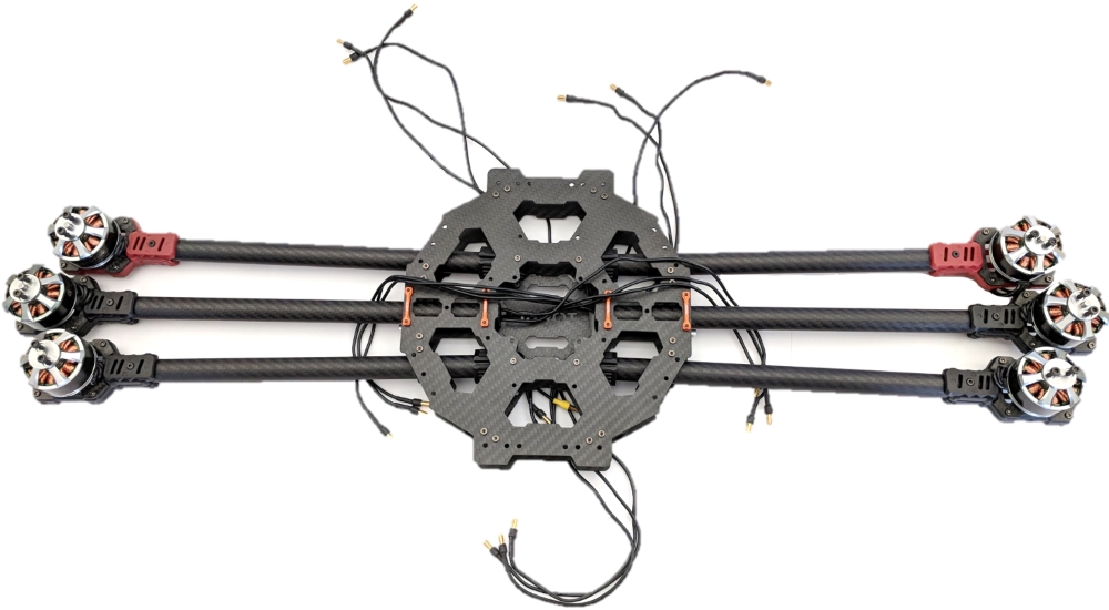
The hexacopter frame is constructed from a Tarot FY690S Hexacopter carbon fiber frame, with modifications made to integrate telemetry tracking equipment. The UAV-RT system uses a Pixhawk Mini flight controller manufactured by 3DRobotics Inc. The Pixhawk flight controller is an open-hardware system capable of running either PX4 or Arducopter flight controller firmware, but the hexarotor currently uses the Arducopter firmware because the software provides integrated flight modes and autonomous vehicle control not supported by PX4.
1. Preparing the Frame
IMPORTANT: When inserting or tightening screws that are metal on metal contact, its highly recommended to use the blue thread locker as it will ensure stability of the fastens.
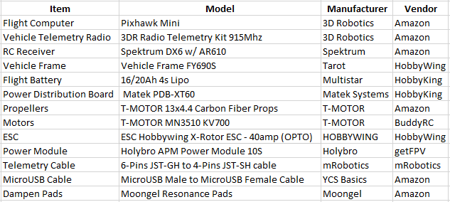
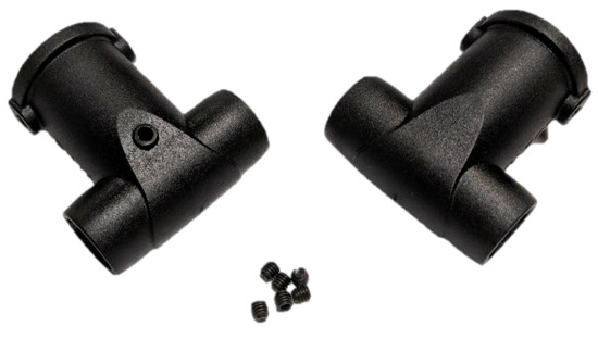
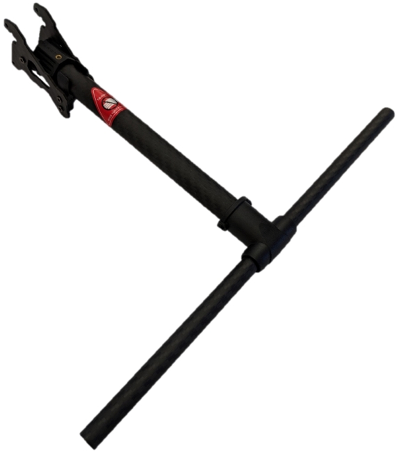
Getting into the vehicle assembly itself, in the vehicle frame box you receive from Tarot, you are given an assortment of bags with various parts included. The first part we want to assemble is the arms that will mount onto the vehicle. These arms will look like this when they come in the package.

Some arms will have a grated motor mount attached already and some will not, as shown above. Keep these in mind since they are much different than the four arms without a mount on them. We will be attaching a motor mount on each of the four arms with a small black stub on the end. Looking at each motor mount, some are black and some are red. The red motor mounts will indicate the front of the vehicle, so plan accordingly when assembling these later, there will only be two of these used. The end of those four arms will have a hole on the clean end which a screw will go through. Just take an end piece and insert it on the clean end of the arm and align the hole of the end piece with the hole in the arm and insert a long screw included with the same bag the end piece was found. Tighten the screw with a dab of thread locker and repeat for all four arms. REMEMBER, two arms should have red motor mounts and the rest should be black.
The next part we want to look at is the landing gear that will be used on the vehicle. The picture below is what each leg will look like.
Disassembling the metallic parts is the first step. BE SURE TO KEEP THE SCREWS WHEN DISASSEMBLING.
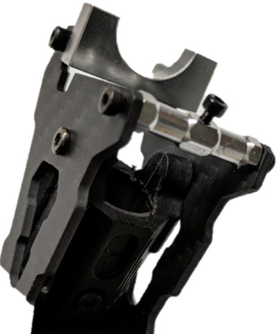
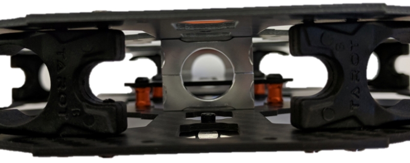
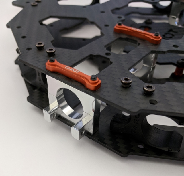
Once both landing gear legs are disassembled, next is to attach the metallic part with hexagonal ends, to the center frame.

The metallic brace should be mounted on the bottom side of the center frame like shown in the figure above. Mirror this same assembly on the opposite end of the bottom, like shown below.
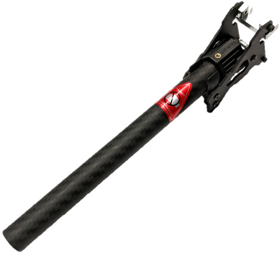
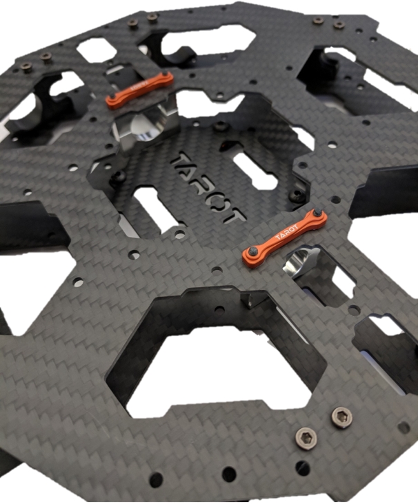
The next step is to find the metallic parts that look like a half pipe, not confusing it with the parts from the landing gear. Be sure to loosen the screws on these ends to make it easier to assemble these parts.
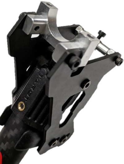
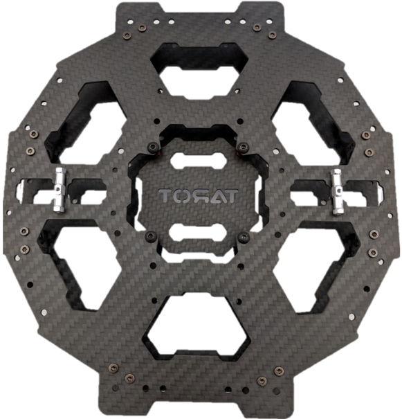
The two metallic half circles will be attached on the inside of the frame near the center, like shown below.
Mirroring this same assembly on the other side will look like the figure below.
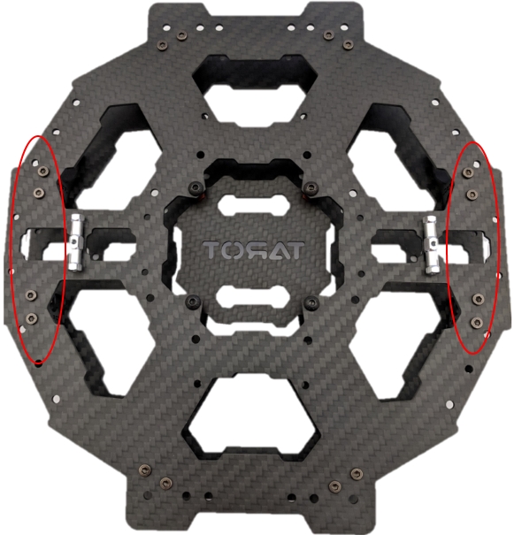
Next step is to take the landing gear piece that looked like a half circle and assemble them on the outside of the frame of each side. Looking like the figure below.
This is important to complete now because this is where those arms with just a clean end will be inserted like the figure below shows. But we will not be attaching arms just yet, picture below is just to emphasize what the arms will be used for in the future.

2. Landing Gear Part 1
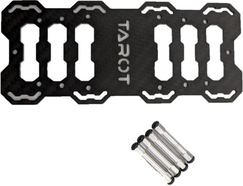
Now that the center frame is ready for those side arms, we can jump over to assembling the landing gear legs to prepare them for attachment at the end. This step can be done at any point in the assembly but will be shown at this step. The leg that was previously disassembled will be used along with the thin carbon fiber bars and three holed plastic pieces to look like the third and fourth picture below.
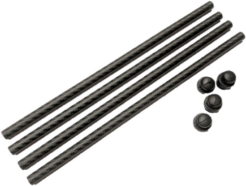

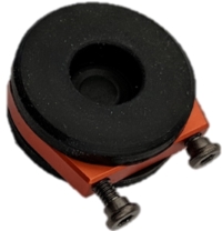
The three tiny screws are incredibly difficult which require a 1.5mm hex screwdriver. Included will be these rubber ends that can be attached on the ends of the legs as shown below.

With this, now the landing gear legs are assembled, and they are ready to be mounted at the very end.
3. Motors and Arms
The next step is the motors, you will need to gather your six motors, motors mounting plates, and all the arms of the copter.
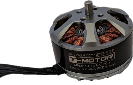
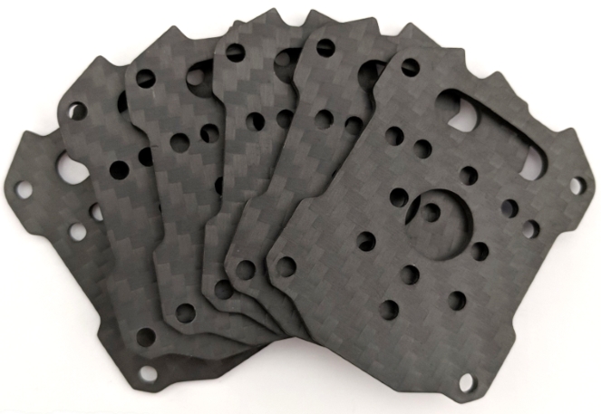
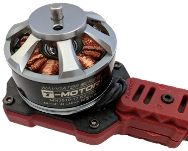
Each plate should be mounted onto the motor first and then attached to each arm. The motor plate has a lot of holes for diverse types of motors, the motors listed in this guide will fit. Using the correct hex driver, attach each motor with a motor plate.

For cleaner assembly, instead of letting the motor wires float to the side, they should be threaded through the hole in the motor plate and then attached to the frame arms. If they are threaded through the hole there will be no wires on the outside of the frame. In either case, take the wires and thread them through the arm, you may need to remove the screws in the arm for easier threading.

Removing these screws just a little bit will clear the path for the wires to fall through. Once the wires are threaded through, attaching the motors to the arm itself is next, which requires a few screws.
Once all the arms are assembled, they can be mounted onto the center frame. Start with the side arms mentioned as before, the key is to make sure they are inserted the same amount on both ends. The best measurement of this is to align it with the center frame as shown below. Look at the red line.
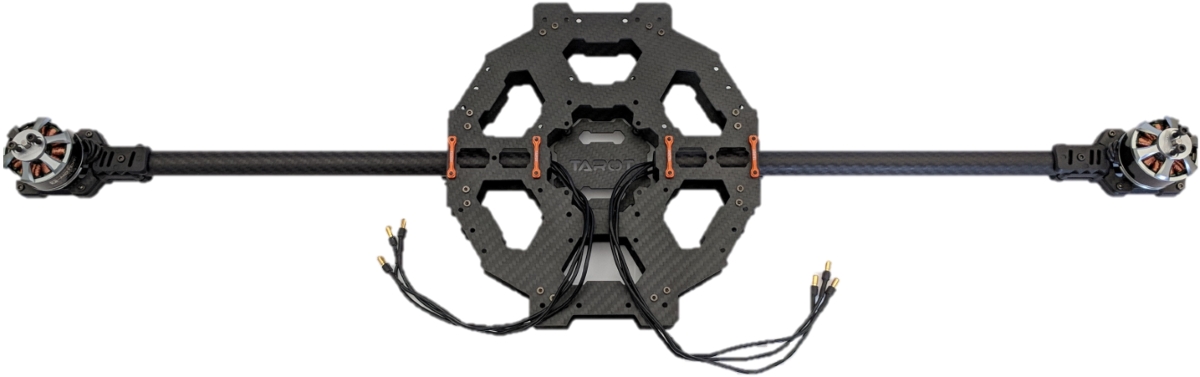
Before tightening the screws, make sure the arms are level with the center frame by using a leveler. The next four arms are easy to attach, they merely require a couple screws each that were included in the package. They attach onto the center frame like the picture below. There is a screw on the top and bottom of the frame.
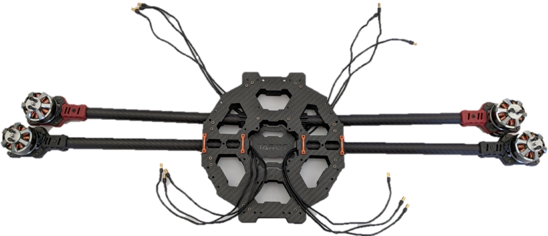
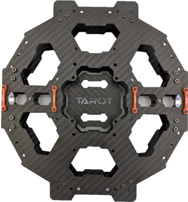
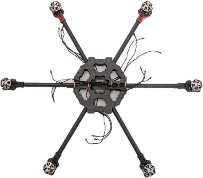
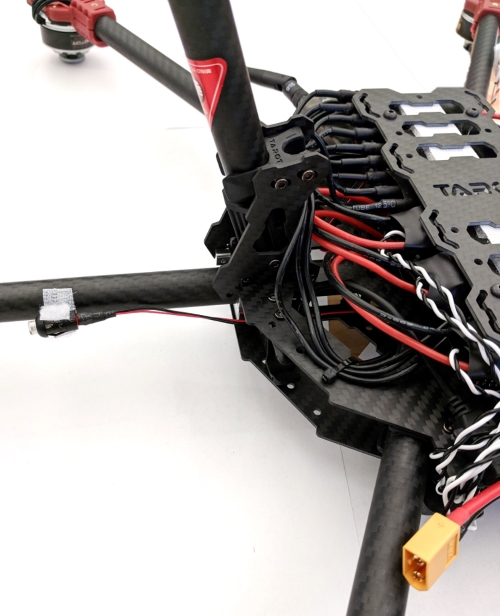
Once all the arms are mounted correctly the frame should look like something like this.
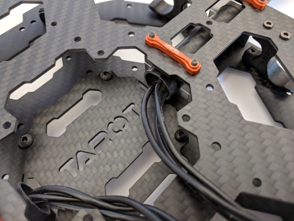
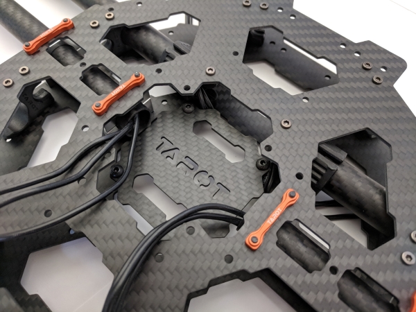
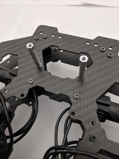
4. Rail Guards
Once these arms are installed, we can attach the rail guards onto the top of the vehicle frame. The rail guards are these pieces.
These are attached to the front and back of the center frame. In the picture below the frame is upside down.
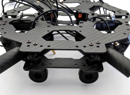
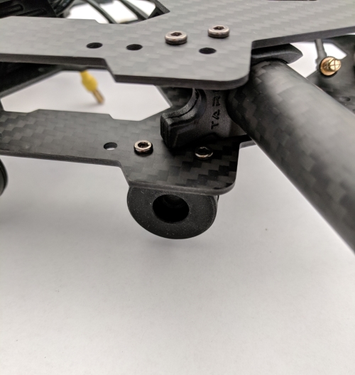
One essential step to mention is that soon we will need to remove the center plate that has the name “Tarot” on it, in the figures above you may notice the center plate is missing from the middle. This is essential to attaching the power distribution board to and making the electrical components easier to mount.
5. ESCs
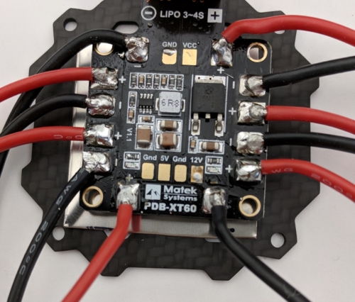
The next major step is the ESCs and mounting these to the frame. The first task to accomplish is to solder the ESCs to the power distribution board (PDB). This manual will assume you understand how to solder and will not be going into detail about soldering. This is the PDB that will be used in this assembly.
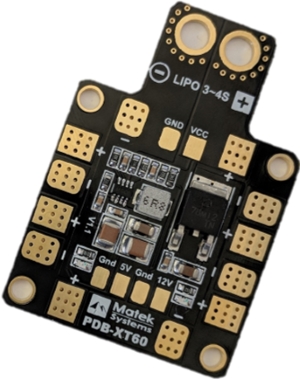
The ESCs power cables will be soldered to each of pads on the square part while the power ports at the top will be left alone for now. This the figure below, the red lines connected an individual ESC, so the same format can be followed if need be.
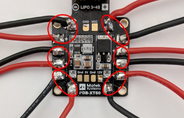
Next the power connector can be attached to the ports separate from the pads. With the connector provided with the PDB, it should look like the figure below.
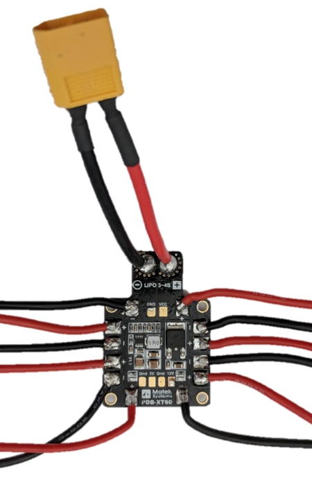
Once the PDB is soldered like above, it can be attached to the center plate detached from earlier. You may want to use some type of metal sheet in between the PDB and the center plate, the assembly completed from this guide uses Velcro and a small adhesive to mount them together. It should look like this below.
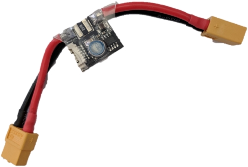
Be sure to keep the APM power module close by as that can be attached to the PDB now before mounting or after mounting.
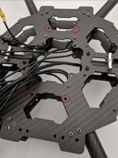
Before you put the PDB and ESCs on the frame, we will want to mount the bottom plate where the ESCs will rest.
The screw holes that the silver bars will be placed are shown below.
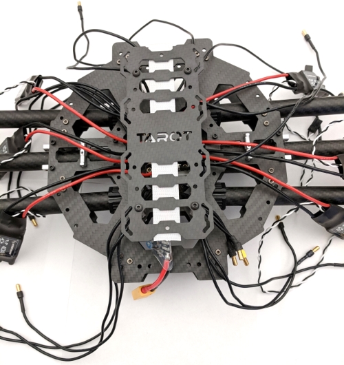
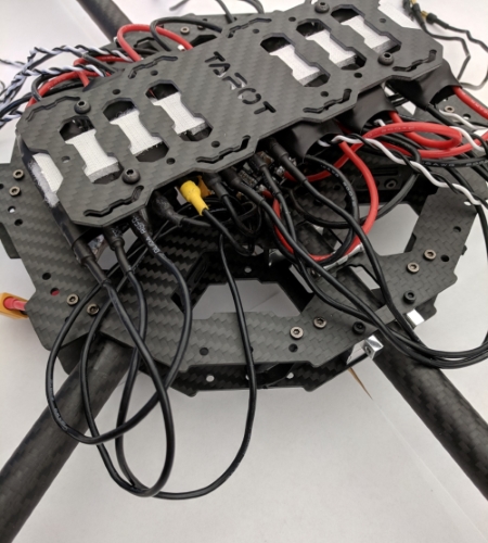
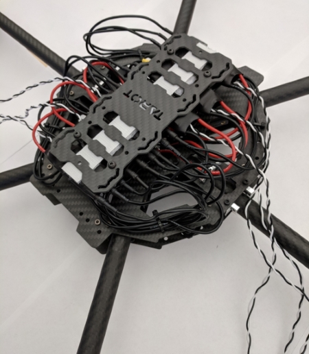
Once this plate is mounted, we can now insert the PDB and ESCS. Now with the frame upside down, you can thread this bunch of ESCs into the center frame to get the PDB to lay in the center where the center plate used to be as shown below.
Notice the strip of Velcro along the plate that was mounted just recently. The Velcro will be used to keep the ESCs in place, each ESC has a small strip of Velcro on it to make it stick to the plate.
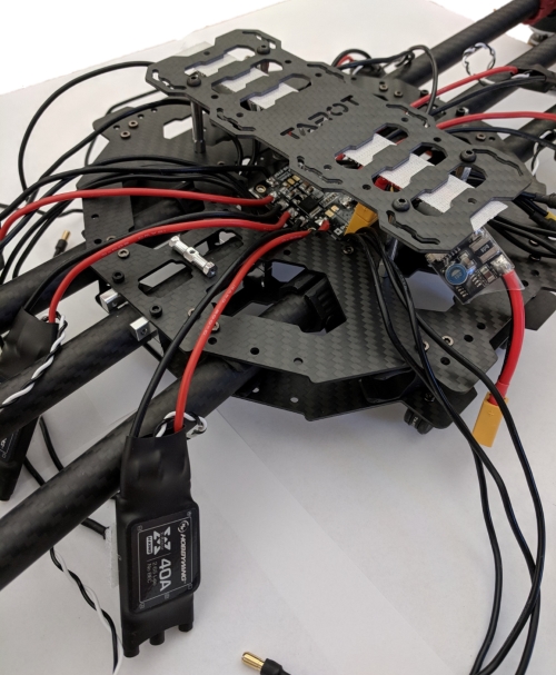
6. Attaching the ESCs
The next step is to now place the ESCs onto the plate to securely mount them. Again, in this assembly we used Velcro. Once the ESCs are mounted onto the plate, you can take each of the motors and insert the three cables of each motor into each ESC. While is does not matter what motors you plug into which ESC, it matters the order of the cables as a different order may make the motor spin clockwise or counterclockwise. As this is an easy adjustment we will not be worrying about it now until calibrations towards the end. The assembly should be looking something like these few pictures shown below.

At this point in the assembly it would be wise to look at which motor was connected to what ESC and take note of it to keep track of. This will be important when hooking up the black and white receiver cable of each ESC. When keeping track of it reference this figure and assign the ESC to what number motor it is connected to. This figure will be important to reference later as well when calibrating the motors.

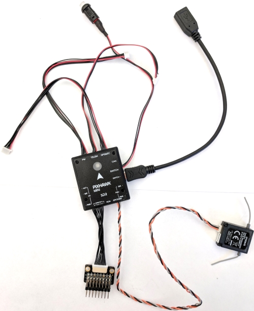
7. Setting up the Pixhawk
For now, lets move on to the Pixhawk portion of the assembly. At this point we can start looking at mounting the Pixhawk, which has several different wires and connections with it. Included below is a picture of every wire needed with the Pixhawk and how it looks when connected. An important piece is that the Pixhawk does not come included with a 6pin JST_GH to 4pin JST-GH to use with the telemetry radio mentioned in this guide. You may need to buy this or create one depending on the type of telemetry radio used or autopilot used.

The next step we will be focusing on will be connecting the receiver cables of each ESC. The receiver is this part of the pixhawk.
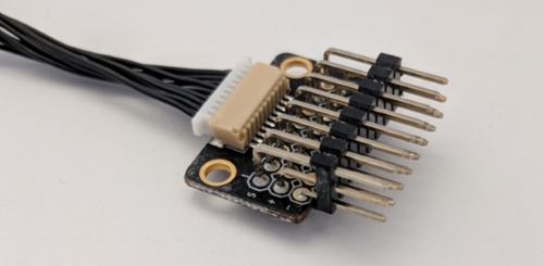
When plugging in each cable, pay attention to the numbers on the receiver shown above. Each number must correspond to the motor in that reference image shown earlier. If you kept track of what motor was connected to what ESC, this will be simple to do. Another important thing to know is that when plugging in the cable of the ESC, the white cable will go on the top end while the black cable will go on the bottom as shown below.
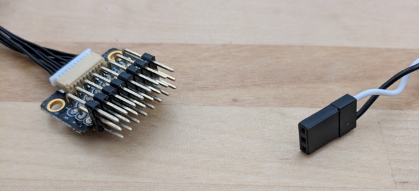
With each receiver cable plugged in, the assembly should look like this.
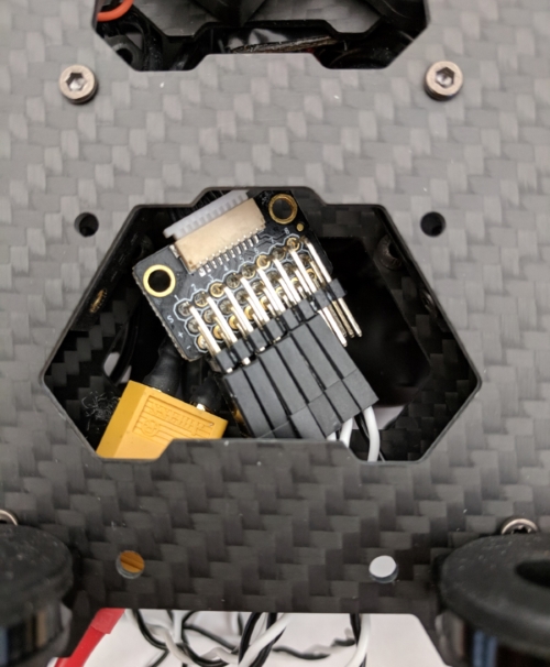
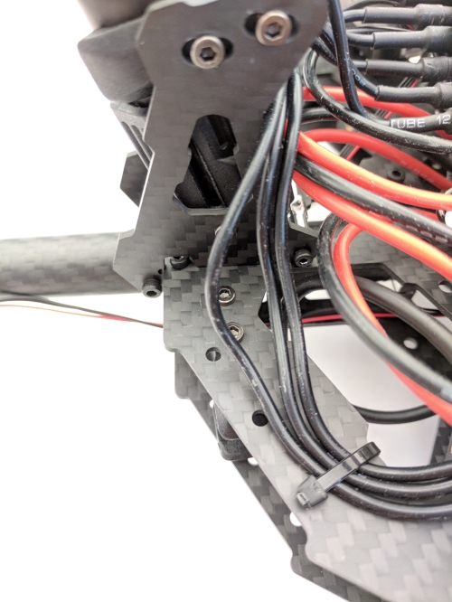
To get the receiver in that position, the Pixhawk is mounted on top of the vehicle frame on the center plate where the PDB rests. It is also mounted at a 45-degree angle for wiring purposes.
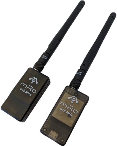
8. Telemetry Radio
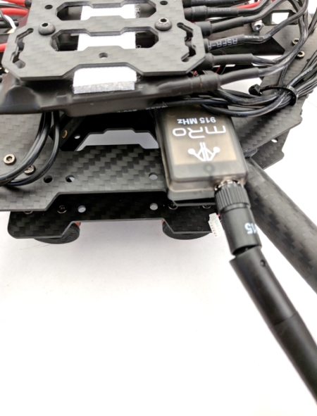
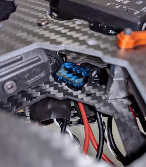
The next step is to take the one of the telemetry radios and connect it to the Pixhawk and attach it somewhere onto the frame.
This assembly attached it inside the frame facing outwards to the front of the vehicle. A picture is shown below of the radio sitting inside the frame.
9. Landing Gear Part 2
Before fully mounting the Pixhawk, we can mount the landing gear onto the vehicle. We need to line up the legs, so they face outwards and attach to the silver pieces that we attached to the frame at the beginning. There will be four screws for each leg, and they will attach to the frame like shown below. Remember to use thread locker.
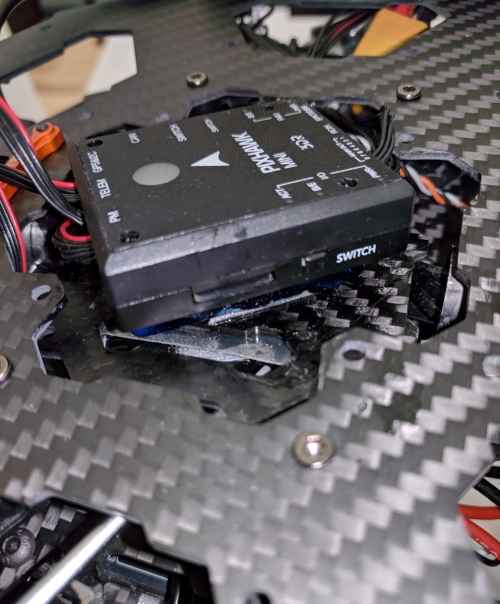
10. Mounting the Pixhawk
Now that the vehicle has the landing gear mounted, we can mount the Pixhawk onto the center plate. This will require some finesse and patience. In this assembly, we used a dampen pad along with double sided tape to attach the Pixhawk to the center plate. Then instead of attaching the center plate with the screws originally used, we used a small piece of a dampen pad, tape and some glue which keeps the center plate in place but allow for some vibrations to occur.
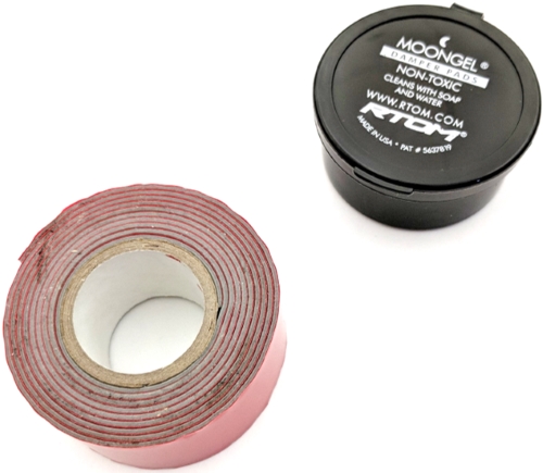
This will prevent the vibrations of the vehicle from affecting the Pixhawk to potentially alter its accelerometer readings and ruining the flight path and orientation. The Pixhawk mounted can be seen below.
The next picture shown is the center plate and the small dampen pads that are used to keep the plate in place.
With this, the next and last step is to mount the propellers, but before that can happen, we must first calibrate the firmware and test out the motors to ensure it is ready for a test flight.
11. Calibrations
You will want to download mission planner on a computer with a micro usb cable to be able to plug into the pixhawk of the vehicle. Reference Download Mission Planner for download instructions.
When you initially start up mission planner, you will need to go through the wizard of setting up your drone. You can either use the wizard or go into the “Initial Setup” tab and navigate to the “Mandatory Hardware” section on the left. There will be six types of setting and calibration to set. Follow each one’s instructions to ensure full calibration. IMPORTANT NOTE, however you have your autopilot mounted, you must make sure you set the orientation in the params as shown below.
For this step, please refer to our Initial Calibration page for setting up the calibrations and setting the required parameters. For additional information about configuration please see our Advanced Configuration page for more.
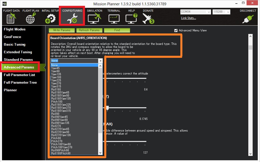
In our assembly, our pixhawk is mounted at 45 from the front, so we chose “Yaw45”. This is important or else your vehicle will not fly correctly.
12. Propeller Installation
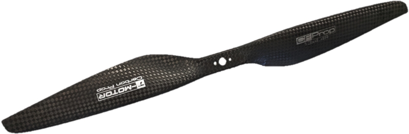
Once the calibrations have been completed, the last step is to attach the propellers to the motors. When ordering propellers, they usually come in pairs which include a clockwise propeller and a counter-clockwise propeller. It is important to know which propeller is which since wrong assembly will prevent the UAV from flying correctly. The image below is used as a reference for attaching the propellers, which was used previously for calibrating the motor directions.
While using the above figure for reference, it now time to install the propellers on each motor. Each propeller is made for a clockwise rotation or counter-clockwise rotation, it is important to be able to discern which propeller is which. The figure below is a counter-clockwise propeller.
The next step is to identify the parts that come with the propellers. The parts shown below are what we will be using to install the propellers onto the motors.
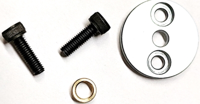
A couple screws, one of the round plates and a small gold colored ring. The gold colored ring is important as it is used on the motor to keep the propeller a little more stable by keeping it tightly secured. It is the first part to be placed onto the motor as shown below.
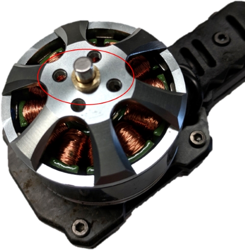
Now you can place the propeller onto the motor and align the holes of the propeller with the holes of the motor. Remember to check and make sure the clockwise orientation is correct for both the propeller and motor.
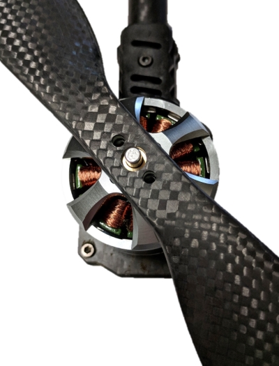
The last step now is to place the metal plate on top of the propeller and once again align the holes, while also attaching the screws.
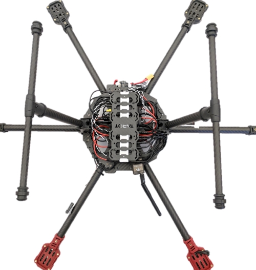
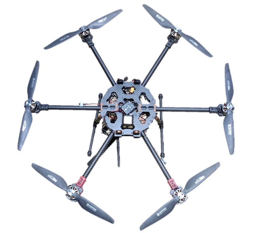
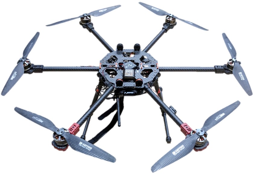
The pictures below show the complete vehicle without the scientific payload for reference as to how it should look.
Antenna Attachment
Now that the vehicle is built, we can attach the VHF antenna mount to the bottom. You first need to use a 3-D printer to create the antenna mount that is attached to the bottom of the vehicle. Please reference our Downloads page for the 3-D printer file. Once the antenna mount is completed, you can attach the VHF antenna to the mount. There are a couple of screws that attach to the antenna and the mount. Once that is complete, you can now mount it to the bottom of the vehicle.

