This section will discuss using Mission Planner to visualize vehicle data during flight and will describe how to create autonomous flight plans specific to vehicle tracking. For information regarding what Mission Planner is, reference Ground Control Station Background. The documentation below is specific to creating flight plans for wildlife tracking but broad Mission Planning documentation is available.
Flight Data Screen
The Mission Planner (MP) flight data screen can be utilized by the pilot to obtain vehicle information during flight. The vehicle first needs to be connected over the 3DR Telemetry Radios (SiK Radio) using the Mission Planner connect feature. Once connected the live terminal can provide current GPS location, artificial horizon, and a variety of other features. The figure below from the Arducopter website showcases some of the data present on the flight terminal. For detailed usage reference the GCS Flight Data Screen documentation.

Flight Plans
The following section details two flight plans that can be utilized for telemetry data collection. For the differences between a Flight Plan and Flight Modes reference Flight Modes vs Flight Plans. The first flight plan is more frequently utilized by the team for tag localization and takes advantage of the range and directionaliity of an H-antenna. The second method provides an example of performing a search using an omni-directional antenna. Both tests involve using the custom drone described in The Vehicle. These flight plans include utilizing a drone outfitted with a directional and omni-directional antenna and seeks to maximize and minimize the telemetry signal respectively. Both flight plans use Mission Planner’s autonomous flight mode interface, and again detailed information for creating autonomous flights can be found on Arducopter.
Yaw Flight Plan
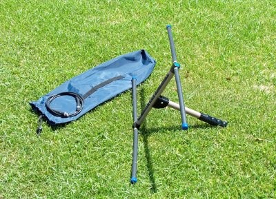
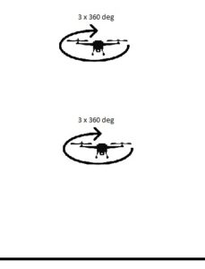
The first flight pattern uses the VHF antenna (shown below) and a series of yaw flight plans to locate the direction where a signal is maximized. By determining at what heading the maximum signal is detected the likely direction of arrival (DOA) can be computed and hence the estimated direction of the tag’s location is determined (for detailed information on this processing read Radio Telemetry documentation). This flight plan includes 3 complete yaw rotations at two various altitudes as shown in the bottom right figure. As described in the introduction, this flight plan is created using Mission Planner’s autonomous flight mode and although this flight plan demonstrates creating only two waypoints, a similar method can be used for multiply waypoints. To build this flight mode, you will need to follow these steps listed below.
STEPS TO CREATE YAW FLIGHT PLAN
Step 1: Select the Flight Plan tab, located at the top left of the Mission Planner interface.
Step 2: Find the location you wish to build your flight plan on the map (note: sections of google maps can be pre-fetched and accessed in the field when an internet connection is unavailable example below)
Step 3: Right click at your desired home location and select “Set Home Here” (the home direction may be set automatically if your copter is already connected to mission planner.)
Step 4: Next, change your Default Altitude to the desired value (10m recommended) and set the height from “Absolute” to “Relative”.
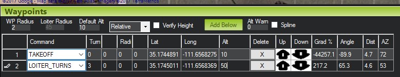
Step 5: Click on the map near the home location and you will see that a waypoint is added below, with options to change the action that occurs at that waypoint (shown below).

Step 6: For this waypoint select take off.
Step 7: Click to add the second wave point and change the type to Loiter-Turns. Next to this waypoint insert 3 in the Turn column, 0 in the Radius column, and the first desired altitude in the Alt column.
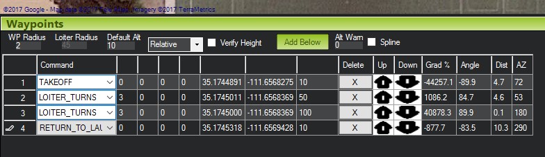
Step 8: Add a third waypoint and drag the location on top of wave point 2. Follow the same procedure in step 7 but changing the Alt to the second desired altitude.
Step 9: Add a fourth waypoint anywhere and change the type to “Return_to_Launch.” The final flight plan should look like the figure below.
Step 10: You will want to make sure your copter is connected to the Mission Planner interface.
Step 11: Now select “Write WPs” on the right side of the screen to load the mission plan to the copter. (Note: you can also select “Save WP File” for later use in the field. To recall the file later simply select “Read WPs” instead of following steps 1-9.)
Step 12: The copter is now prepared to begin autonomous flight.
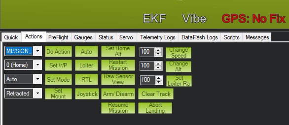
Step 13: From the Flight Data Tab, select Actions. You can now push the “arm/disarm” button to arm the copter (make sure the copter is in stabilize or loiter mode before arming.)
Step 14: In the first drop-down select “Mission_Start” and push do action to begin the mission, like shown below.
Step 15: The copter will complete the Yaw Flight Pattern landing and disarming at the original launch location.
Lawn-Mower Flight Plan
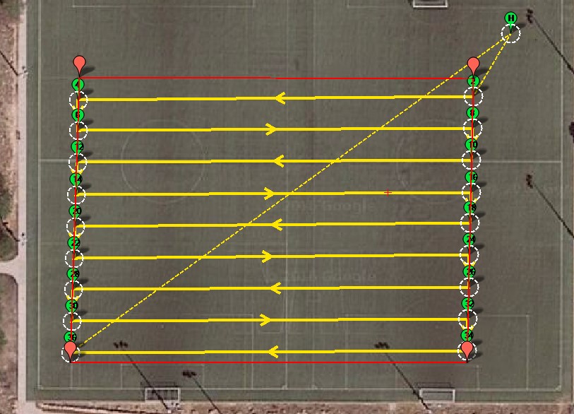
The lawn-mower flight plan utilizes an omni-directional antenna and takes advantage of the null obtained when flying directly over a beacon. The goal of a lawn-mower flight pattern is to obtain a localized minimum from the radio signal, where it can be determined that the animal of interest is directly under the drone. The flight pattern takes advantage of Mission Planner's auto-grid feature, and although this feature is optimized for cameras it can easily be utilized for this purpose. Steps are provided below to build this flight mode for yourself.
STEPS TO CREATE LAWN-MOWER FLIGHT PLAN
Step 1: Select the Flight Plan tab, located at the top left of the Mission Planner interface.
Step 2: Find the location you wish to build your flight plan on the map (note: sections of google maps can be pre-fetched and accessed in the field when an internet connection is unavailable, see here.)
Step 3: Once you have the desired area on your screen, right-click and select “Draw Polygon” > “Add Polygon Point”. This feature will allow you to place points that auto-generates a polygon over the desired region (note: If you need to reset your polygon “Draw Polygon” > “Clear Polygon”).
Step 4: Next change your Default Altitude to the desired value (10m recommended) and set the height from “Absolute” to “Relative”.
Step 5: Upon completing the polygon right click on the shape select “Auto WP” > “Survey (Grid)”.
Step 6: The menu immediately gives choices for various cameras but we can ignore this for our purposes. Instead, enter the desired flying altitude then check the advanced options box towards the bottom of the pop-up window.
Step 7: With the new tabs select “Grid Options” and entered the desired distance between lines (10m is recommended.) Then select “Accept”.
Step 8: Make sure your coper is connected to the Mission Planner interface.
Step 9: Now select “Write WPs” on the right side of the screen to load the mission plan to the copter. (note: you can also select “Save WP File” for later use in the field. To recall the file later simply select “Read WPs” instead of following steps 1-9.)
Step 10: The copter is now prepared to begin the autonomous flight.
Step 11: From the Flight Data Tab, select Actions. You can now push the “arm/disarm” button to arm the copter (make sure the copter is in stabilize or loiter mode before arming.)
Step 12: In the first drop-down menu select “Mission Start” and push "Do Action" to begin the mission.

Step 13: The copter will complete the Lawn-Mower Flight Plan landing and disarming at the original launch location.
Note: If you wish to control the direction of the copter during the flight you can change the “DO_SET_CAM_TRIGG_DIST” (this is automatically set to trigger a camera if one was connected) way points to “CONDITION_YAW” and set the desired yaw you wish the copter to hold during the flight.